Marine Equipment & Systems

Fuel Oil Electric Heating System

Stable fuel-temperature control with staged power and dry-heating protection built in

Selected capability

Fuel Oil Electric Heating System

Stable fuel-temperature control with staged power and dry-heating protection built in

Electrical heating for fuel oil, lubricating oil and related marine media, using staged PLC control and layered interlocks based on pressure, outlet temperature and heater-surface temperature.

01Grouped control supports load modulation and isolating individual banks
02Low watt density supports gentler heating and lower coking risk
03Layered pressure/temperature interlocks reduce dry-heating and overheating risk
Discuss this project
Fuel Oil Electric Heating System
Equipment / engineering context
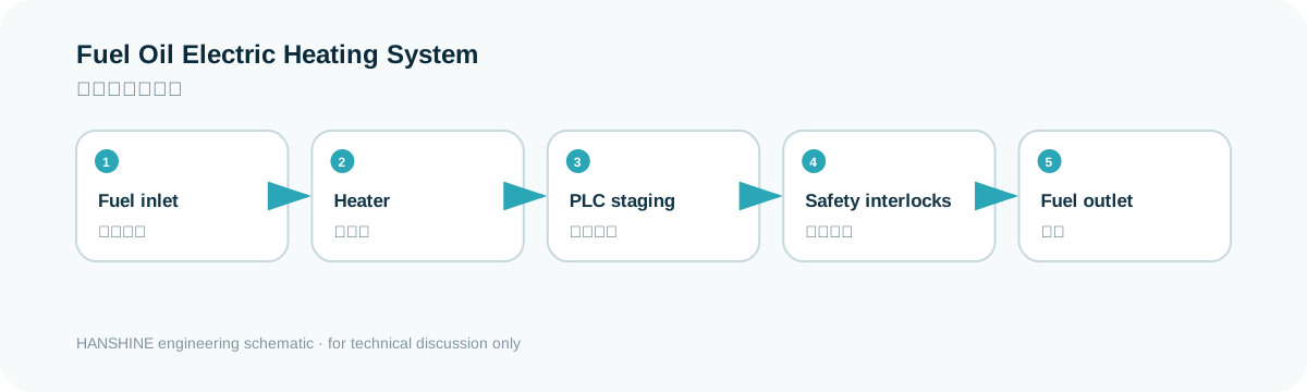
Fuel Oil Electric Heating System schematic
Technical principle / system relationship
System relationship

Make the interfaces clear before equipment selection.

This flow is a quick view of the system boundary. Final quantities, interfaces and configuration remain vessel- and project-specific.

01Fuel inlet
02Heater
03PLC staging
04Safety interlocks
05Fuel outlet
01

Typical configuration & scope

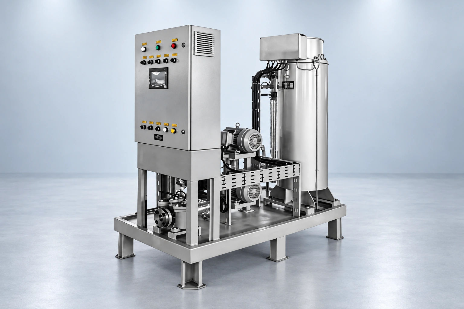
  • Stainless-steel heater body
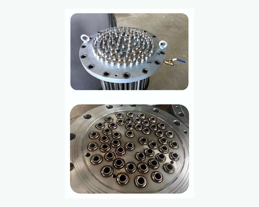
  • Grouped heating elements and reinforced welded transition sleeves
  • PLC control cabinet and HMI
  • Pressure, outlet-temperature and element-surface protection
02

Information required

  • Medium, flow rate and inlet/outlet temperatures
  • Working pressure and allowable pressure drop
  • Supply voltage/frequency and target duty
  • Class requirement, space and flange interfaces
03

Engineering focus

  • Size duty from heat balance rather than rule-of-thumb only
  • Control element watt density and media velocity
  • Maintain manufacturing records for welding, annealing, pressure and insulation tests
04

Standards & technical basis

  • Class product approval as required
  • Marine electrical/heater safety practice

Applicable rules, certificates and approval scope are confirmed against vessel class, flag and contract requirements.

System advantages

Marine electric heating engineered around safety, service life and control accuracy.

From CCS compliance and PLC power regulation to element loading and welding quality, the system is designed for dependable long-term operation onboard.

01

CCS Compliance Leadership

One of the earliest domestic manufacturers to meet the latest CCS requirements for marine electric-heating equipment.

02

PLC Grouped Power Control

Grouped PLC control enables stepless power regulation with high accuracy and reduced impact on the onboard electrical network.

03

Four-Layer Safety Protection

Four coordinated protection layers cover pressure, heater-surface temperature, fuel outlet temperature and sensor-fault shutdown.

04

Leak-Resistant Welding

A dedicated transition-sleeve and automated welding process strengthens the element-to-flange connection and minimizes leakage risk.

05

Controlled Annealing Process

A controlled annealing process maintains accurate annealing temperature for stable material performance and service life.

06

Low Surface Heat Load

Heating elements are selected to a high standard with low surface loading for gentler heating, reduced coking and improved operating safety.

07

Compact & Serviceable

Compact equipment reduces installation demand while keeping operation straightforward, maintenance accessible and performance reliable.

Customized solution

Controlled fuel heating designed around the vessel — not a one-size-fits-all heater.

We match heating duty, element surface loading, control logic, sensors and protection to the vessel's fuel properties, operating profile, installation space and power conditions. For the shipowner, this means more stable fuel temperature, faster control response, lower routine maintenance demand and easier integration into existing automation systems.

Stable temperature & viscosityLower maintenance demandFaster control responseRetrofit-friendly integration
Engineering advantages

Four design details that directly improve safety and service life.

The differences are in the control architecture, protection logic, element loading and manufacturing process — the details that matter most after years of onboard operation.

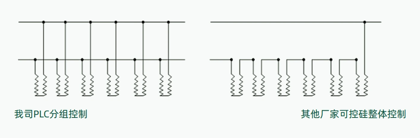
PLC grouped control diagram
01

PLC Grouped Control

Heating groups can be switched independently. Any individual group can be taken out of service without stopping the complete heater, extending service life and reducing maintenance cost.

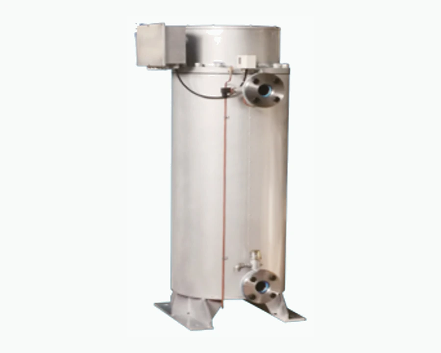
Marine electric heater safety protection
02

Four-Layer Protection

  1. Heating surface is arranged below the outlet level.
  2. Outlet pressure sensing allows heating only when pressurized oil flow is present.
  3. High heating-element surface temperature triggers alarm and shutdown.
  4. High fuel outlet temperature or sensor fault triggers alarm and shutdown.
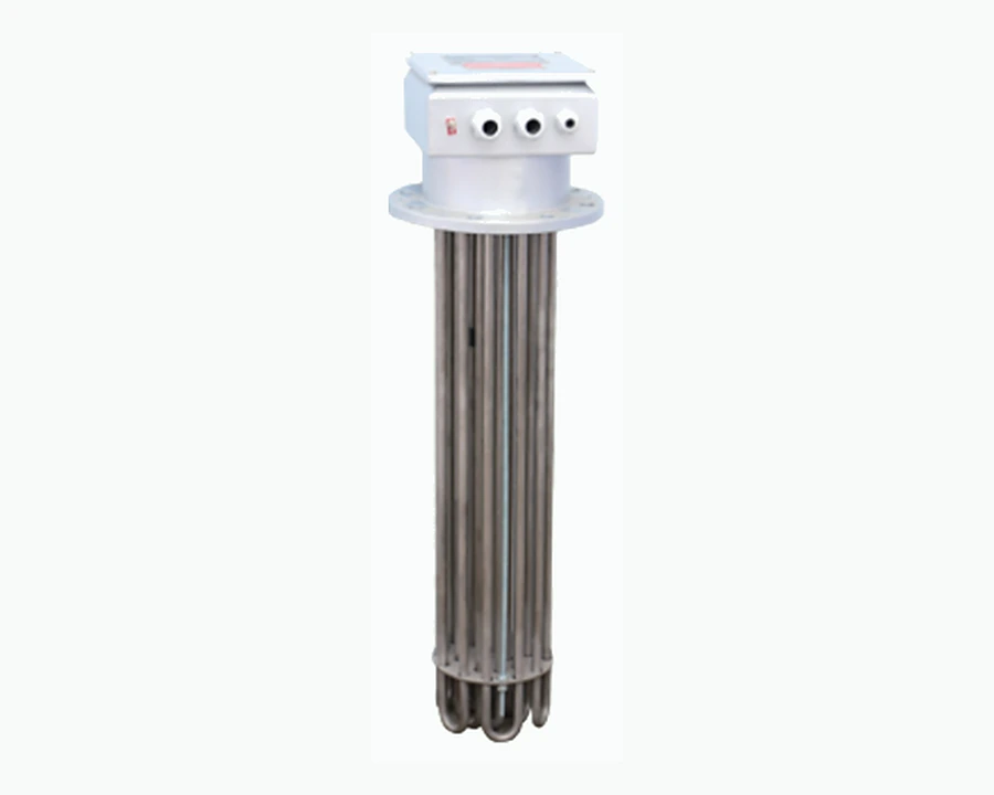
Marine heater element
03

Heating Element Manufacturing

  1. Stainless seamless tube material selected to boiler/heater service requirements.
  2. Magnesium-oxide filling quality is strictly controlled.
  3. Oil-heating element surface load is kept at ≤2 W/cm² for gentler heating, reduced coking and less fuel degradation.
Heating element flange welding process
04

Element Welding Process

  1. A thicker transition sleeve strengthens the connection between the heating element and flange to reduce leakage risk.
  2. Automatic welding delivers consistent, clean and reliable weld quality.
Solution configuration

A complete heating package configured for the vessel and operating duty.

The final package can integrate heater body, PLC control cabinet, sensors, protection devices, interfaces, drawings, commissioning support and recommended spares according to the vessel arrangement.

Heating mediumFuel oil, water, air, gas and project-specific media
Power supplyConfigured to onboard AC power system
Power regulationContactor stages, SSR or thyristor control
MaterialsCarbon steel, stainless steel or project-specific alloy
InstallationInline, skid-mounted or tank-mounted
Typical information only. Final values are confirmed in the project technical agreement.
One-stop project delivery

Five controlled stages from vessel assessment to lifecycle support.

01

Consultation & Onboard Survey

Collect vessel parameters, operating profile and energy demand, then inspect installation space, piping, electrical conditions and construction feasibility onboard to establish an accurate project basis.

02

Customized System Design

Develop a vessel-specific design based on survey data, confirm technical parameters, evaluate energy-saving potential and issue a structured technical-commercial proposal.

03

Standardized Manufacturing

Apply full-process quality control from incoming materials and fabrication through inspection and factory release to maintain stable performance and consistent build quality.

04

Integrated Installation, Commissioning & Verification

Provide turnkey supply and installation covering equipment, engineering, cables, valves and foundations, or standardized installation guidance and remote support. Commission the system and verify operating and energy-performance data after installation.

05

Data Visibility & Lifecycle Support

Operating and energy data can be uploaded to a management platform for visual monitoring. The complete unit carries a 12-month warranty; eligible failed parts are replaced during the warranty period with responsive technical support for long-term stable operation.