Marine Equipment & Systems

Marine VFD Energy-saving System

Match pump and fan output to actual vessel demand

Selected capability

Marine VFD Energy-saving System

Match pump and fan output to actual vessel demand

Uses temperature, pressure or differential-pressure feedback to regulate motor speed, with PLC/HMI coordination for multi-drive sequencing, bypass and condition monitoring. Typical applications include cooling-water pumps, engine-room fans and other variable-duty auxiliaries.

01Variable speed reduces throttling/damper losses
02Soft acceleration can reduce mechanical stress
03Status and energy data can be integrated to HMI or ship monitoring
Discuss this project
Marine VFD Energy-saving System
Equipment / engineering context
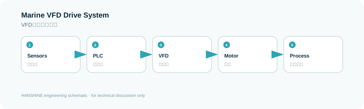
Marine VFD Energy-saving System schematic
Technical principle / system relationship
System relationship

Make the interfaces clear before equipment selection.

This flow is a quick view of the system boundary. Final quantities, interfaces and configuration remain vessel- and project-specific.

01Sensors
02PLC
03VFD
04Motor
05Process
01

Typical configuration & scope

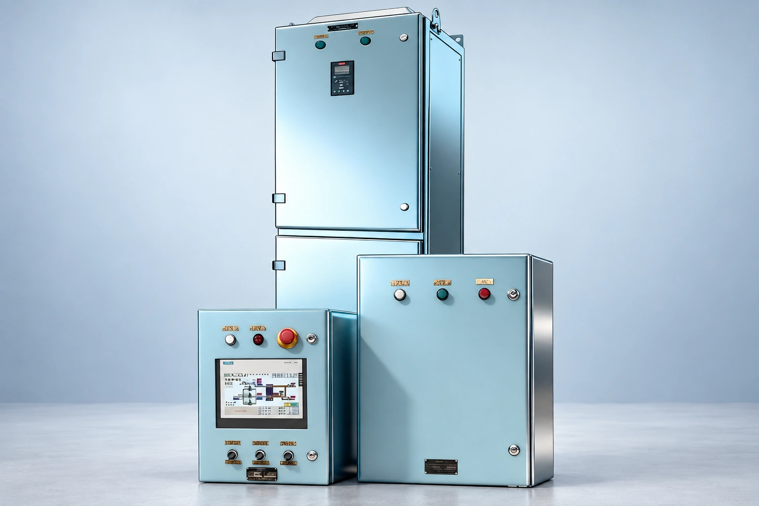
  • VFD cabinet and bypass circuit
  • PLC/HMI control station
  • PT100, pressure / DP transmitters
  • Communication and remote interface
02

Information required

  • Motor nameplate, quantity and starting method
  • Current frequency/load and valve/damper position
  • Target temperature/pressure
  • Ship-grid voltage/frequency, fault level and harmonic limits
03

Engineering focus

  • Savings should be calculated from pump/fan curves and duty profile
  • Bypass should preserve critical auxiliary operation during VFD faults
  • Marine environmental protection, EMC and harmonics belong in cabinet design
04

Standards & technical basis

  • IEC 60092 series where applicable
  • Class electrical rules

Applicable rules, certificates and approval scope are confirmed against vessel class, flag and contract requirements.

Energy performance

Turn variable-speed control into measurable operating savings.

VFDs match pump and fan speed to actual demand instead of forcing motors to run continuously at full speed. For vessels with highly variable auxiliary loads, the energy-saving potential can be substantial.

Energy-saving potential 70%

Up to 70% lower energy use

In suitable high-variation load profiles, variable-speed operation can significantly reduce unnecessary motor power consumption compared with conventional fixed-speed operation.

Payback potential 6–12 mo

Fast retrofit payback potential

For projects with sufficient operating hours and energy-saving headroom, estimated retrofit payback can be approximately 6–12 months, creating continuing savings thereafter.

Marine retrofit focus

Cooling-water and engine-room ventilation are the two core retrofit scenarios.

The solution is tailored for vessel-specific requirements such as coordinated operation of multiple pumps and fans, highly variable operating conditions and high stability requirements, helping maintain reliable operation while improving energy efficiency.

Actual energy savings and payback depend on the vessel load profile, operating hours, electricity/fuel cost, equipment condition and retrofit scope, and are confirmed through project-specific calculation and onboard data.

Solution configuration

Configure the drive package around the vessel, not the other way around.

The final package is defined from onboard survey data, motor loads, control philosophy, interface conditions and class requirements.

01
Core application solutions

Control strategies for the two highest-value auxiliary systems.

Cooling-water system

Demand-based flow and pump coordination

  • Dynamic regulationAdjust motor speed and the number of online pumps from real operating demand, avoiding unnecessary pumping power.
  • Coordinated controlMultiple drives communicate and balance accumulated running hours to reduce long-term loading on individual equipment.
  • HMI visibilityDisplay operating status, trends, alarms and adjustable parameters on the HMI for controlled and transparent operation.
Engine-room ventilation

Automatic ventilation matched to changing machinery-space demand

  • PID controlAutomatically regulate fans from temperature, pressure or differential-pressure feedback to respond precisely to operating changes.
  • Bypass protectionProvide bypass or fallback operating modes so ventilation can continue if the variable-speed control path is unavailable.
  • Remote integrationRemote control and communication interfaces can be integrated with the vessel central monitoring or automation system.
02
Core package

Drive hardware, sensing and protection configured as one system.

VFD equipment

Marine-ready drive selection

  • BrandsOptions include Siemens SINAMICS, VACON, Schneider Electric, ABB and Danfoss according to the project specification.
  • Power rangeTypical retrofit coverage: 0.75–250 kW for common marine auxiliary motors.
  • Class supportClass-approved equipment or project certification support can be provided where required.
Sensors

Feedback signals for closed-loop optimisation

  • PT100Temperature monitoring for equipment and process control.
  • 4–20 mAPressure transmitters provide stable feedback for speed regulation.
  • Differential pressureDifferential-pressure feedback supports flow balancing and operating-point optimisation.
System characteristics

Maintainable, stable and energy-conscious

  • MaintainabilityModular hardware and clear diagnostic logic simplify fault tracing and lifecycle maintenance.
  • ReliabilitySmooth variable-speed control replaces repeated fixed-speed switching and adapts better to changing marine loads.
  • EfficiencyReduce unnecessary electrical demand and associated emissions while maintaining the required process performance.
Project delivery

From onboard survey to verified savings and lifecycle support.

The delivery model can be adapted to vessel schedule, docking window, installation conditions and the owner’s preferred scope of supply.

01

Pre-project communication & onboard survey

Collect vessel parameters, operating conditions and energy demand; inspect installation space and construction constraints; and complete the initial technical and savings assessment.

02

Customised solution design

Use survey data and vessel operating characteristics to define the control strategy, equipment selection, interfaces and expected efficiency improvement for the specific vessel and route profile.

03

Integrated installation & commissioning

Provide an integrated scope covering equipment, engineering, cabling, foundations, installation and commissioning, or supply standardised installation guidance and remote support according to the owner’s preferred delivery model.

04

Energy-performance verification

Use operating and energy data collected by the monitoring system to quantify pre- and post-retrofit performance and verify the achieved energy-saving result against the agreed evaluation method.

05

Lifecycle service support

Eligible equipment is covered by a three-year replacement service rather than repair, excluding damage caused by misuse or force majeure. Scheduled six-month and annual inspection, cleaning, performance testing and system-update services can be provided together with continuous online technical support.